Every once in a while I come across a component that gets me dreaming. This morning I received a press release about such a component: a wireless EEPROM from STMicroelectronics. The M24LR64-R is a 64 Kbit EEPROM with password protection and a dual interface. It has a standard 400 kHz I2C bus for reading and writing the device, but it also has an ISO 15693 compatible 13.56 MHz contactless interface. You can actually read and write this chip using RFID and near field communications (NFC) techniques without needing to power it. I think that is pretty cool.
Every time when I had to draw a PCB with memory, especially the kind with lots of address and data pins, interfacing in parallel to a processor, I started dreaming about wireless memory. Wouldn’t it be great if you only had to plunk a memory chip on a board, somewhere in the vicinity of the processor and not wire anything? Instead of transmitting over the air you could probably use a copper or some other metal plane as a better communication medium. Or you could make the PCB out of wood or paper and stick the components on it with ecological glue.
Maybe some day wireless will be so cheap that you can have intelligent wireless resistors, capacitors and other parts that could be mesh-networked to build a circuit. You simply put the components in a bag or box, like rice or sugar, and it all would work without wires and soldering. OK, that is a bit far fetched, but who knows what we will have 50 years from now? This RFID EEPROM is definitely a step in the right direction.
This kind of dreaming reminds me of the time when I was a kid and a friend of mine had a Tandy electronics experimentation kit with resistors, transistors and other parts. It used springs for wiring. We would wire at random the parts together while fantasizing about the amazing things our circuit would do. Of course nothing ever happened (and somehow we never smoked anything), but it kept us busy after school. Being nerds we had not yet discovered girls, but I did get a glimpse of his mum naked. Maybe one of our random circuits did work after all…
Tuesday, December 7, 2010
Tuesday, November 23, 2010
PSoC 5 Design Challenge
Here is yet another design contest:
Cypress Semiconductor announced the ARM Cortex-M3/ PSoC 5 Design Challenge, a contest to find the most innovative and useful designs from the millions of possibilities available to designers using the Cypress PSoC 5 architecture powered by the ARM Cortex-M3 processor. The contest is presented in conjunction with EE Times and ARM with the Grand Prize to be awarded in May, 2011. A total of over $10,000 in cash and prizes will be awarded throughout the contest, including the $2,500 Grand Prize. More information, including how to enter the contest and how to become a judge, as well as lively interaction from participants and the engineering community is available here.
Cypress Semiconductor announced the ARM Cortex-M3/ PSoC 5 Design Challenge, a contest to find the most innovative and useful designs from the millions of possibilities available to designers using the Cypress PSoC 5 architecture powered by the ARM Cortex-M3 processor. The contest is presented in conjunction with EE Times and ARM with the Grand Prize to be awarded in May, 2011. A total of over $10,000 in cash and prizes will be awarded throughout the contest, including the $2,500 Grand Prize. More information, including how to enter the contest and how to become a judge, as well as lively interaction from participants and the engineering community is available here.
Monday, November 15, 2010
Sceptre library update
The December issue of Elektor (now on sale) includes a 32-page supplement dedicated to microcontroller projects. In this supplement you will find two articles related to the Sceptre.
First of all there is a 4-page article about Oberon-07, a high-level PASCAL-like programming language, but object oriented. If you know MODULA-2 you will quickly find your marks, if you don't, well then it is pretty straightforward too. Oberon-07 has special features for microcontroller programming. It is f.i. very simple to manipulate bits and registers. Oberon-07 compiles very quickly in very efficient code. The Astrobe IDE makes things even easier thanks to its many libraries and comfy editing options. Serial comms, I2C, math & strings, and much more, it is all ready for you. Go check it out.
The second Sceptre article presents an extension card with a Nokia 6100 mobile phone color LCD, a Blackberry trackball and a 16 Mbit flash memory chip on it. All is controlled over an SPI bus, so the card doesn't use a lot of the Sceptre's I/O. Thanks to a nice open-source driver it is easily possible to display images at a framerate of more than 10 per second!
The fun thing of this card is that it doubles as a universal Arduino shield adapter for the Sceptre. A 16-bit I/O expander from Microchip together with some more Sceptre GPIO make the Sceptre compatible with an Arduino. You can now simply plug an Arduino shield on the Sceptre and use it. As there are many shields available, this unlocks a huge playground for Sceptre enthusiasts.
CAD (Eagle) files and software for this project are freely available together with a library update for the Sceptre. New functions (f.i. RFID), new examples (including a real MIDI file player!) and improved modules (better Bluetooth) make new applications easier. Go get your download here.
Tuesday, November 2, 2010
Renesas RX Design Contest
The Design Contest seems to be the new weapon of choice for microcontroller manufacturers to get attention for their products. NXP is currently running the mbed Design Challenge and two weeks ago Renesas announced their RX Design Contest. Over $110,000 worth of prizes will be distributed amongst the participants.
The Design Contest is also a good way for electronics enthusiasts to get a nice piece of hardware for free. NXP is handing out LPC1768 Cortex-M3 mbed modules for free and the first 1,000 participants of the Renesas contest get a complimentary RX62NRDK development board.

This board supports most flavors of USB, has a color graphics display, LEDs, buttons, SD-card connector and whatever you may need in a project. Random particpants will also get a full licence for Micrium uC/Probe together with the book uC/OS-III RTOS for the Renesas RX.
The contest finalists will be announced on March 13, 2011. The final judging will be at the ESC in San Jose, California on May 3, 2011.
(See also here and here for other contests.)
Wednesday, October 20, 2010
Eagle switches to XML
Last week a rumor started spreading about Eagle, the popular schematic capture and PCB drawing package used by thousands of electronics enthusiasts, switching to a text-based file format. We at Elektor asked CadSoft, the editor of Eagle, about this rumour and got it confirmed. Somewhere in the hopefully near future Eagle will start using an XML-based file format for storing its drawings. The reason for this change is, according to CadSoft, that the binary format has reached its limits.
I find this reason a bit strange. Why would a text format be more flexible than a binary format? I mean, text is just limited binary, right?
Of course a text-based format is human readable, which is an advantage when trying to debug a broken file. But will this help in real life with a multi-megabyte sized file? (BTW, I have never yet had to debug a PCB file.)
A text-based format will be cross-platform as it avoids byte ordering issues, a good thing. Using XML is probably a good idea too, because it is a well known format and many tools & libraries for fiddling with XML files are readily available.
For the user a text-based format is interesting as it may help speed up certain repetitive tasks like net labeling or copying blocks. Users will start writing utilities for manipulating Eagle files.
Will they? Probably. They always do.
But Eagle already offers a powerful scripting language that lets you do lots of things without learning the file format first, so why bother? By writing a script you can already export everything yourself to a human readable format. And that is exactly what RS did for DesignSpark, the competitor of Eagle Freemium by Farnell (who bought CadSoft some time ago). RS offers scripts that allow you to export Eagle files as ASCII data. This is what it looks like:
EAGLE_INTERMEDIATE_ASCII "my_board.brd"
(asciiHeader
(fileUnits IN)
)
(library Library_1
(padStyleDef "Oval1"
(holeDiam 0.0314961)
(padShape (layerNumRef 1) (padShapeType Oval) (shapeWidth 0.0514961) (shapeHeight 0.102992))
)
(padStyleDef "Round1"
(holeDiam 0.125984)
(padShape (layerNumRef 1) (padShapeType Ellipse) (shapeWidth 0.133984) (shapeHeight 0.133984))
)
(padStyleDef "Rectangle1"
(holeDiam 0)
(padShape (layerNumRef 1) (padShapeType Rect) (shapeWidth 0.07) (shapeHeight 0.1))
(padShape (layerNumRef 16) (padShapeType Ellipse) (shapeWidth 0) (shapeHeight 0))
)
…
That is not so different from XML, is it?
The only reason I can think of why Farnell/CadSoft wants to switch to XML is that they hope that the heavyweights like Cadence or Pads will start writing Eagle import filters for their products. These products already know XML, it would be easy enough to add Eagle support. And that would be a good sales argument for Eagle. Start simple and low-budget with Eagle and when you’re ready to move on to something more serious you won’t lose your work.
It is all about compatibility.
Thursday, October 7, 2010
Build a dishwashing surveillance system
Every once in while I spend an afternoon or evening just browsing eBay. I do some searches on keywords concerning things that may interest me and I look through the results. When I find something interesting I click on the item for more details. Often I come across items that are sold by Chinese companies that sell lots of other things too. These are my favorite sellers. There are many Chinese eBay shops that sell exactly the same products, they probably are all related, but every once in a while I discover a new “family” of shops with different products.
My latest find is a series of cheap microcontroller boards equipped with a small camera and a 2.8” color TFT display. The camera, 640x320 pixels, is actually a small module that is plugged on top of the board, while the display (320x240 pixels, 262K colors) sits on the other side. You can make a camcorder out of it, because it has a micro SD card connector for storage.

I bought the ATmega32 board including a USBasp ISP programming cable for less than 35 euros (shipping included). It is a complete development system with full documentation and source code in C (with comments in garbage characters, probably Chinese). When it arrived I discovered that the display even has a resistive touchpad on it.
Here is a sneak preview of my killer app for this board: a dishwashing surveillance system that checks my dishwashing qualities. It will detect dirt on the dishes and sound an alarm when everything is dry. Pretty cool, huh?

So, what will you do with it?
Monday, September 13, 2010
RFID made simple
More and more people are using the Sceptre ARM7 board from Elektor, which is good. The Sceptre is supported with an open source library in C and I am currently working on adding new functionality to it. As I wrote in a previous article I spent quite some time understanding the BTM222/112 Bluetooth modules and this will soon be included in the library.
I also received a request for RFID support and so I implemented a driver for the EM4095 transceiver (EM Microelectronic) that can read the tags you can buy for cheap on eBay (for instance).
To get me started I bought in Hong-Kong (through eBay of course) for 17.50 euros (shipping included!) a fully functional RFID proximity door entry access system with 10 tags and 5 badges. Only a week later the kit arrived.
This turned out to be a pretty nice product actually; its only downside is its cheap plastic housing that will probably not survive very long outdoors. Rain and intruders will not have a very hard time getting to the electronics.

Top side of PCB

Bottom side of PCB

The antenna is slightly larger than the PCB
Interesting about this unit is that it uses a "discrete" (well, sort of, compared to a single chip solution) radio, built around a 4069 and a 74393. I traced the circuit (see below), but I didn’t measure the capacitors (all SMD) except for C3 which has 2.2 nF (222J) printed on it. It seems hard to believe that this solution is cheaper than using a dedicated chip like the EM4095, but it probably is. Or maybe the design is older?

The processor is a W78E052DDG, a pretty standard 8051-clone by Nuvoton (formerly known as Winbond).
I only used the antenna from the kit (and of course the tags) for my experiments since I had the EM4095 chip on a break-out board and now that I am done, I am looking for an application for my "RFID proximity door entry access system". What about a cat door opener? Hmmm…
P.S. The RFID driver will be included in the Sceptre library. An update is scheduled with the December issue of Elektor (available half of Novembre). If you can't wait that long, just drop me a line.
I also received a request for RFID support and so I implemented a driver for the EM4095 transceiver (EM Microelectronic) that can read the tags you can buy for cheap on eBay (for instance).
To get me started I bought in Hong-Kong (through eBay of course) for 17.50 euros (shipping included!) a fully functional RFID proximity door entry access system with 10 tags and 5 badges. Only a week later the kit arrived.
This turned out to be a pretty nice product actually; its only downside is its cheap plastic housing that will probably not survive very long outdoors. Rain and intruders will not have a very hard time getting to the electronics.


Interesting about this unit is that it uses a "discrete" (well, sort of, compared to a single chip solution) radio, built around a 4069 and a 74393. I traced the circuit (see below), but I didn’t measure the capacitors (all SMD) except for C3 which has 2.2 nF (222J) printed on it. It seems hard to believe that this solution is cheaper than using a dedicated chip like the EM4095, but it probably is. Or maybe the design is older?

The processor is a W78E052DDG, a pretty standard 8051-clone by Nuvoton (formerly known as Winbond).
I only used the antenna from the kit (and of course the tags) for my experiments since I had the EM4095 chip on a break-out board and now that I am done, I am looking for an application for my "RFID proximity door entry access system". What about a cat door opener? Hmmm…
P.S. The RFID driver will be included in the Sceptre library. An update is scheduled with the December issue of Elektor (available half of Novembre). If you can't wait that long, just drop me a line.
Wednesday, August 25, 2010
Rayson BTM222 & BTM112 Bluetooth modules
The Sceptre has a Bluetooth module; in fact it was designed for using a BTM222 or BTM112 Bluetooth module from Rayson. These modules are cheap and easy to find on the internet. They do have one problem though and that is the lack of documentation. The official datasheet only shows one table with AT commands and that’s it. When I did my initial experiments with the modules, I managed to get them going, but I was never quite satisfied with how they were working. A few days ago I decided to give them another go and improve my driver. I spent quite some time googling and I did find some new information. The official documentation is still limited to the single table, but now I know that it is incomplete too!
The BTM222 & BTM112 are part of a large family of modules that are all very similar. Differences are mainly in TX power and integrated antennas or not. It is possible to find some more information by studying the datasheets of the related modules.
Commands not listed in the BTM112/BTM222 dataheet I know of so far are:
+++ – Switch from data mode to command mode (valid only when connected)
AT – Doesn’t do anything but should return “OK”
ATCx, x = [0,1,?] – Flow control (RTS/CTS) disable (0) or enable (1, default)
ATH – Drop current connection (valid only when connected)
ATIx, x = [0,1,2,?] – Information, 0: firmware version, 1: current settings, 2: RSSI (valid only when connected)
(Strictly speaking the ATI command was not undocumented completely, but it was partly lost when the PDF was made.)
ATLx, x = [#,*,8] – Baud rate, #: 1200, *: 2400, 8: 921.6k (0-7 were already documented)
ATO – Switch from command mode to data mode (valid only when connected)
ATSx, x = [0,1,?] – RS232 powerdown disable (0) or enable (1, default)
ATXx, x = [0,1,?] – Escape sequence disable (0) or enable (1, default)
Sparkfun sells the BTM182 which is supposed to have the same firmware as the BTM112. The accompanying documents on their web site list most of the above commands.
A delay of at least 50 ms is needed after each command before the module will accept a new one. This delay is much longer for the commands that reboot the module; after ATR0 for instance the module needs at least 3.5 seconds to recover. Several other commands cause module reboots too: ATC(0,1), ATH(0,1), ATO(0,1), ATZ0.
It is possible that the module gets stuck in some undefined state (try ATZ1) or that the serial port parameters are wrong and you do not know them. The only way to get the module out of there is to pull pin PIO4 high for at least three seconds.
My BTM112 gets stuck in master mode when the connection is broken and it will only respond to the AT command. The only way to get it going again quickly is to restore the connection or to use the PIO4 reset. It seems to become available again after a pretty long wait too. I did not observe this behaviour on the BTM222 even though both modules have the same firmware version 4.22 (which doesn't mean that they have the same firmware).
A typical master mode sequence for a virgin device could look like this (I’ve set de waits a bit long):
ATN=my device (16 characters max, space is allowed)
Wait 100 ms
ATP=6587 (set a PIN code of 4 to 8 digits)
Wait 100 ms
ATR0 – switch to master mode
Wait 3500 ms
ATO1 – disable autoconnect (only available in master mode)
Wait 3500 ms
ATF? – scan for remote devices (this only works when autoconnect is off)
Wait at least 60 s or until you receive "Inquiry End."
ATA1 – connect to the first device found
Wait until you receive “CONNECT 'xxxx-xx-xxxxxx'”
Do data transfer
+++ – switch to command mode
Wait 100 ms
ATI2 – get RSSI for remote device
Wait 100 ms
ATO – switch back to data mode
Wait 100 ms
Do data transfer
+++ – switch to command mode
ATH – disconnect
Wait until you receive “DISCONNECT 'xxxx-xx-xxxxxx'”
Etc.
Note that when you are in autoconnect mode (ATO0) the module may reconnect to the same remote device almost immediately after disconnecting with ATH.

This photo shows two Sceptre boards, one with a BTM112, the other with a BTM222. They are connected (both PIO7 LEDs are on continuously) and the BTM112 is the master. I connected a push button to PIO4 for reset testing.
ATZ0 does not reset all parameters, it resets only C, E, H, O, Q, R & X (I did not check the serial port parameters). RS232 powerdown, remote device addresses, friendly name & PIN code remain unchanged. They also survive power cycles, meaning that if the last used slave device has the same PIN code as the master and autoconnect is on then the master will connect automatically to the last used slave device. No commands to issue at all. This will also work if the modules swapped roles.
PIO5 pulses high when data is being transmitted, it is fixed high during reception. PIO7 provides status information. An LED may be used to visualize the status, but it may also be useful to connect them to your processor. Issuing an ATZ0 will make PIO5 & PIO 7 flash three times, but PIO8 only two before resuming normal operation. PIO8 seems to remain high during normal operation. This is what I observed for PIO7:
- Master idle (autoconnect on) – toggling at about 0.4 Hz (BTM222) or 0.5 Hz (BTM112)
- Master idle (autoconnect off) – fixed low
- Slave idle – toggling at 1.7 Hz (BTM222) or 4.6 Hz (BTM112)
- Connected – fixed high
Besides restoring the factory defaults (3 s press) PIO4 can also be used to reset/reboot the module with a short pulse. An even shorter pulse (6 ms) on PIO4 will cause a disconnect.
If you have any information not listed here, please let me know!
Wednesday, August 11, 2010
Forget about the hardware and learn C
Many people are afraid of 32-bit microcontrollers, or even 16-bit ones. Why? Because they have lots of pins? Lots of registers? If you are an 8-bit PIC assembly language programmer, why do you think it would be more difficult to program a 32-bit controller in assembler? Or is it that the more powerful controllers are meant to be programmed in C instead of assembler? Many people are afraid of C (let’s not even talk about C++). I have been programming in C for too long now to understand why you would be afraid of C, but I do know that it scares many 8-bit developers and newbie programmers.
This is a shame because new controllers nowadays always come with a free C-compiler. It may be limited in some way, but it is free and gets you started. Also, these new controllers come with evaluation kits that are cheaper and cheaper. The MSP-EXP430G2 kit from Texas Instruments for instance costs only $4.30 and includes two (2) 16-bit RISC processors, a PCB with programmer/debugger and a USB cable. Now that’s value for money. Or what about the STM8S-Discovery kit from STMicroelectronics. True, that is a kit for an 8-bit controller, but it costs less than $10 and includes a programmer and a breakaway controller board with capacitive touch sensor.

Hardware is becoming so cheap that it is becoming much like the paper you write on. Unless you’re an artist, you hardly ever care about your paper, the back of an envelope is often good enough. And it will be the same with hardware. You should no longer care about the platform you are working on as long as you can get your application to work. If you learn a language that is supported by all platforms, you can use whatever processor you like instantly and you’re application will be ready much sooner. The language is the pen, write your article and when it is ready send it off to the printer. They will then reproduce your design in the best and cheapest way. They may even decide to change the microcontroller, which is not a problem as your code was written to be portable.
Thursday, July 29, 2010
Add a smartphone to your application
One of the biggest hypes of the moment is of course (or should I say still?) the Apple iPhone. I do not have one, so I do not have an opinion about it, but it seems that many users are crazy about it. This is due to all the non-phone things you can do with it. Recently several electronics related apps have come to my attention but I have my doubts about the usefulness of those. Reading a datasheet on a smartphone? Usually when I need a datasheet I also have a proper computer nearby so why bother using a smartphone for that? I must be missing something here.
But now I heard about an electronics app for iPhone that seems pretty cool, even to me. It is more than an app as it needs a piece of hardware to function. Actually, it is the other way around: it is a piece of hardware that needs the iPhone app to function. Now that is not exactly right either as it is a piece of hardware that can be controlled by the app. Let me rephrase this properly: it is a small computer module that uses the iPhone as a display.
That’s right, the DIL/NetPC DNP/9265 from SSV is an embeddable ARM9-module (Atmel AT91SAM9263) with 32 MB flash and RAM. If you need more, just add an SD card. To connect the module to its environment 3 UARTs, an I2C, an SPI, a CAN, a USB Host interface and several GPIOs are available. Smartphone access is over a 10/100 Mbps Ethernet port. The board runs embedded Linux with extensions developed by SSV.

The smartphone app is developed as a web application using only established Web standards such as HTML, CSS, JavaScript and AJAX. The Apple iPhone SDK based on (proprietary) Objective-C is not needed, meaning that the app can also work on smartphones running Android. Furthermore, installing the app on the phone does not involve Apple’s App Store, but uses simply the on-board Web server. This of course makes life much easier.
An OEM integration kit including the DNP/9265 with lots of tools and documentation is available for application developers. An example application that visualizes system resources and that lets you play with configuration data is preloaded. Communication between the module and the phone is over a 2.4 GHz Wi-Fi connection. In case you didn’t have one already, a WLAN access point is included in the kit.
I can’t wait to get one of these kits for evaluation. Ho, wait a minute, I don’t have an iPhone…
Thursday, July 15, 2010
Microchip Application Library: GOL trouble
In a previous article I discussed the PIC32 Multi Media Board (MMB) from Mikroelektronika. Looking around a bit on the web searching for PIC32 related projects I came across the PIC32 Audio spectrum analyzer project by Andrei Mehiläinen. He used a PIC32MX360F512L on a TechToys PIC24 evaluation board (PIC24-Eval-Board, this board supports 100-pin PIC24 & PIC32) with an additional 320x240 TFT display board with resistive touchscreen and an SSD1928 graphics driver. Andrei’s system is very close to the MMB, the main differences are the processor (the MMB has a 460F512L), the graphics chip (an HX8347D on the MMB) and the way the pins are used. I therefore decided to port Andrei’s code to the MMB. This would be a good summer holiday project (being a nerd I always take a development system to the beach). This summer was going to be dedicated to PIC32 projects.
Studying Andrei’s code I soon felt the urge to improve it a bit, especially the user interface as Andrei’s system didn’t really have one. I first started drawing a grid based on MMB example code and then became serious about it by deciding to develop some generic user interface for measurement systems in the style of modern oscilloscopes. So I downloaded and installed the latest Microchip Applications Library (MAL) (v2010-04-28). Having never used them before, I also watched the web seminar about the GUI architecture of the graphics library. In the help files I found a tutorial explaining how to start a new graphics project and off I went.
In the beginning all went well, but when I wanted to add the library C-source files to the project I discovered that I was apparently not doing things the right way as the project would only accept assembler files. So I started all over again but this time using MPLAB’s Project Wizard and now I could go all the way up to trying to build the project. This is where things started to go really wrong: the tutorial code would not compile at all. Of course this was to be expected as the tutorial is for a PIC24 on an Explorer 16 board (yes it is, read the last sentence of the tutorial) and I had modified it a bit to use with a third party PIC32 board.
The first step to glory would be to get the Hardware Profile right. That was easy enough as I used one from the MMB example code. As mentioned before the MMB has an HX8347D (note the D) graphics chip and the Microchip library seems to support it (it knows the A and D version). It won’t compile however as brackets are missing all over the place (DeviceSelect/DeviceDeselect). Clearly this part of the graphics library was not tested properly before releasing it. I fixed this, but only to find out that I was now missing a definition somewhere and compilation would therefore still not complete. Comparing the new library to the (working) one that came with the MMB I noticed that the new library had some changes that required a definition that has something to do with GFX(E)PMP (now what is that again?). There are two possibilities that I tried both, and both gave me other (but different) errors. This is where I gave up (for the moment, I will continue since my holidays aren’t over yet).
Microchip has put a lot of effort in developing their Applications Library, but it is a shame that I am to dumb to use it. It would have been nice if they would have tested it better and if they had provided a working tutorial. Now I have wasted lots of time without getting anywhere. I now know the ins and outs of the graphics driver selection and other low-level GOL details, but I still haven’t been able to draw a single button. Surely it is all very easy, but why didn’t they explain it a bit better? Or maybe it only works properly on Microchip evaluation boards?
At the time of writing I have not figured it out yet, so if you know what I am doing wrong, please let me know. Also, if you happen to know where the API description is that is mentioned in the web seminar, drop me a line.
Thursday, June 3, 2010
PIC32 MultiMedia Board (MMB)
You may know MikroElektronika from their big development boards for PIC, AVR and ARM microcontrollers; you may even own one. I have one of those boards too, the EasyPIC4 that measures about 19 by 23 cm. This is pretty big and not something that you would use in a project. You can develop your project on it, but you have to build your own hardware if you want to actually use it in an application.
They also do some smaller boards. One particular interesting one is the PIC32 MultiMedia board (MMB) and I managed to get one to play with. For some reason the PIC32 does not get a lot of attention, but maybe this board will change that? It is about 9 by 12 cm and well thought out. On the solder side it has a 320x240 pixel TFT display with touch screen, a mini joystick, 6 LEDs and a temperature sensor. On the component side live all the other parts: the PIC32, the power supply and connectors. It has a power socket, a 9-pin RS-232 connector, an SD-card connector, a mini-USB male and a full-size USB host connector, a microphone input (mono) and a stereo headphones output. There is also an ICD programming port and there is room for an MRF24J40MA ZigBee module from Microchip. All the connectors are on the two sides (top & bottom) of the board, the left & right edges have each a row of holes for pin headers so that you can piggyback another board in case you need one.
When you power the board (with a USB cable f.i.), it does a slideshow of some nice photographs. That is all that it does, but it is pretty hypnotizing: butterfly, flower, tree, chameleon, city, oh… butterly again.
The CDROM labeled “software” does not contain development tools. It has a large amount of examples and documentation, but not only for this board, but for all the MirkoE boards. As I happen to have an ICD3 pod I decided to reprogram the board with the Mandelbrot demo. Loading the precompiled HEX file into the board was easy once the ICD3 pod was done reconfiguring itself. Manipulating the joystick now starts the Mandelbrot demo. With the joystick you can scroll in four directions and pushing it zooms in. It is reasonably fast.

Loading the example code in MPLAB was a bit more problematic as the example makes use of some libraries that were not where they were supposed to be. However, after a bit of relocating files I managed to compile the Mandelbrot demo.
The demo is actually a Microchip demo and a well informed source told me that the reason for this is that the board was originally designed by Microchip, but was outsourced to MikroElektronika due to a lack of resources at Microchip. I have seen a Microchip movie demo on this board, but I do not have the code yet.
There is also a test program on the CDROM. Loading this will light up all the LEDs and fiddling with the joystick you can skip, pass and fail certain tests.
More demos are available on the web page for this board. They let you play Rubik's cube or listen to Boney M and Freddy Mercury. BTW, make sure that the two jumpers behind the headphones socket are in the "UP" position, i.e. closest to de board edge, otherwise you will not hear anything. (See the manual if in doubt.)
One negative point: when I tried to insert the headphones with a jack of the right (3.5 mm) diameter in the headphones socket, the whole thing came off. Luckily it didn't cause any damage to the parts behind it, but it was clearly a case of bad joints. Before inserting anything, check the joints and resolder if necessary. This is probably also a good idea for the microphone socket.
I have tried most of the other demo's too and they are pretty nice. One demo showing off the Microchip graphics object layer gives a good impression of the possibilities of the graphics library.
Conclusion: if you want to give the PIC32 a go, this is definitely a good starting point. The board is reasonably priced ($150) and you could do some nice things with it. I do not really see why you would want to make an MP3 or MP4 player out of it, but transforming it into a DSO or a logic analyzer would sure be an interesting project. The touchscreen with the graphics library allows for very slick user interfaces.
Thursday, May 20, 2010
USB 2.0 drop-in for legacy DB9 RS232 connector
It is official! FTDI launches a USB 2.0 module to replace DB9 RS232 connector on legacy boards.

I was given a sneak preview of this module during the Embedded World show at Nuremberg (see here) and immediately felt that this was going to be a killer product.
The module features a standard USB “mini-B” type connector in a module that fits the PCB footprint of a standard 9-pin DB9 connector. The module offers a fast and simple method to add USB 2.0 connectivity to any existing PCB board that has a DB9 RS232 connector.
Two modules are available to replace male or female DB9 connectors. They contain all the electronics needed to carry out the conversion between RS232 and USB. The modules are based on the popular FT232R USB 2.0 to serial UART converter IC from FTDI, which handles the USB protocol conversion. The FT232R device converts from USB to a serial UART interface, which is then level-shifted into RS232 signal levels, within the module. Power to the module is supplied by the USB connection. The modules support a maximum transfer rate of 1 Mbits/s on the RS232 interface.

The DB9-USB-RS232 modules are supplied complete with FTDI's royalty free drivers, which enable a device to be integrated as an additional, (virtual) COM port into an existing software application. The range of drivers includes Microsoft WHQL certified drivers for Windows based operating systems, drivers for Linux and Mac OS operating systems.
Pricing for DB9-USB-M (male) and DB9-USB-F (female) starts at $22.04 for single quantities.
Further information on the DB9-USB-RS232 modules is available on the FTDI website.
Tuesday, May 4, 2010
Fast prototyping with mbed
Tipped off by my friend Gregory I recently bought an LED panel with 32x64 two-color pixels (that is a total of 4096 LEDs!, ref. DE-DP100 from Sure Electronics). I wanted to make some sort of message board out of it, but I was not sure what would be the easiest way. And then suddenly it struck me: why not use an mbed module? The mbed module would offer me programming in C/C++ and a USB file system that would be perfect for storing message files written on a PC. mbed is for fast prototyping and this would be a nice project to see if mbed’s promises would hold true.
Although the LED panel is supposed to run from 5 V and an mbed module from 3V3, studying the LED panel’s PCB revealed that it was built with HC logic only and so it should be possible to run it from 3V3. That was one problem out of the way, no level shifters needed, and I hooked up the mbed to the LED panel with just 12 wires. Note that the mbed module itself is powered from the USB port.

The LED panel has an SPI-like interface and is rather easy (albeit a bit bizarre) to control. It took me some time to figure out that the datasheet provided by the vendor had the CLK and the LATCH lines swapped, but after that I was able to put pixels where I wanted them and in the color of my choice (red, green, orange and black).

The next step was to add a font so that I could write text. If you have ever bitmapped a font you know how tedious a work that is, so I turned to the web. A quick search found me a freeware utility called The Dot Factory and 10 minutes later I had a C source file ready with all the printable characters from an 8-point Arial font (but that could have been any of the fonts available on my PC). That is so much faster than doing it by hand! Another 15 minutes of coding later I was able to print a string on the display anywhere I wanted.
Now I needed a way to get text from a file on the display, together with some commands to control the way the text would be shown. This meant adding an mbed file system object to my code (1 line). Of course I wanted text scrolling, color & position control so I decided to use an INI file for this. A new search on the internet found me a neat little C library named inih that turned out to be very ergonomic: importing and integrating it into my mbed project took a mere 5 minutes; I am definitely going to keep this library!
The final task now was to implement text scrolling properly. This was actually not too difficult using a cheat and thanks to the way the font was implemented. About one hour later I had it all working the way I wanted.

This is the point where features started creeping in. It would be nice to have several pages of text, scrolling should be possible in both directions, scroll speed per line, etc., etc. This is also the point where I started wasting time. Add feature, compile, check, change, compile, check, change, … After some hours of this I decided to stop and freeze the project; you have to draw the line somewhere.
The result is pretty satisfying. The message board can now display seven pages of four lines of text. For each line you can specify a color, an (x,y) position and a scroll speed and direction. Two global parameters allow you to control overall scrolling speed and display brightness, but these are not so useful. I added a push button to browse the pages. Watch this short video to see the result.
The mbed environment really helped to finish this project quickly, the hardware is ridiculously simple and the software is pretty small. The executable is 51 KB and needs 5.5 KB of RAM (mainly for message storage). All in all I think I spend about one day cooking this up, that’s not too bad, isn’t it?
You can download the source code from here.
Sunday, April 18, 2010
Porting code...
...or how to waste lots of time.
Writing portable code is more than just sticking to strict ANSI-C. If you look at the sources of programs or libraries that compile on different platforms, you will find lots of ifdef statements that provide the portability. It is actually pretty difficult to write portable code.
Currently I am into ARM development and I try to target just one OS: mine, on one platform: mine. But I want to use different compilers. I try to write code as portable as possible, without adding compiler specific things, but that just isn’t possible, especially when you target an embedded platform.
Initially I developped some code for GCC. Then I decided that it would be nice if I could use the Keil uVision tools as well. Getting my GCC code to compile with the RealView compiler (used by the uVision tools) was not too difficult, but getting it to work, was.
The problems were caused by, as always, the interrupts. In my code a timer and a UART use interrupts. With the GCC tools both worked fine, with the Keil tools only the UART worked. Uh oh... long debug hours ahead...
I remembered that the GCC code had an interrupt wrapper in the startup code, so all I had to do was to replace the Keil startup code with the GCC startup code. Easier said than done, because it turned out that the Keil assembler did not like the GCC assembly code. This code was definitely not tool-portable (even though the origin of the code clearly was Keil.).
Right, forget about GCC’s special interrupt code, let’s do it the Keil way. I found a Keil timer example that worked on my platform and I copied the code across to my GCC code and … it did not work. I examined the assembler code generated by the compiler for both cases and noticed that the entry and exit code was not the same depending on if the code was integrated in my GCC code or in the Keil example. Yet it was the same C-code, verbatim, since I copied it across, remember?
Or was it?
After stripping down my GCC code (and many hours of hair tearing) I finally discovered that the GCC code had defined away the __irq keyword! Aaargh! So that’s why I didn’t get the right entry and exit code for my ISR!
OK, so I quickly fixed this and now everything would work, right? Wrong!
Obviously there was another problem. My code was now working a bit, but it hung in a delay function. This delay function waited for the timer to reach a certain value before continuing. After some debugging I found that the problem was not so much the delay function itself, but returning from it, it made the program crash. Hmm, that smelled like stack problems.
To make a long story short, the hanging was caused by a function call from within the timer ISR to update a 10 ms timer. After many more debugging I finally found the reason: it was the example code that I had copied! The example proudly mentioned that it handled nested interrupts and I thought that that was mighty fine. But as it turned out, the way the example handled nested interrupts it could not handle function calls from within an ISR... Once the nested interrupts disabled, my Keil code finally worked as my GCC code.
In the end I did not have to make a lot of changes to my original code to port it to a different compiler. It was enough to set the include paths right, define away a GCC __extension__ keyword, add a wint_t typedef, re-allow the __irq keyword and disable nested interrupts, but these last two took me many hours to figure out. At least I now finally understand why the GCC startup code has this special interrupt handling code...
Thursday, April 8, 2010
The InterSceptre is almost ready!
It has been a busy period the last few weeks and I did not have the time to update this blog. Although it is still a rather busy time, I decided to write something anyway because I started working on the prototype of the InterSceptre.

Click for a better view. Notice the valid data on the LCD.
I received the PCB and the parts last Tuesday and I assembled the board. Even though the board is not very complicated, there are a lot of things to test. The first tests are promising. The power supply is fine and the board runs from 3V3 or 5V. There are three different 5V entry points (2x USB & one external power supply) and switch over between these inputs works without resetting the Sceptre board (or the PC).
Also working is the I2C port with discrete level shifter. It is discrete because I tried to avoid SMD parts on this board and through-hole integrated level shifters are hard to find. To test it I use the Pocket Terminal which is part of Elektor project 080253 Running-in bench. This terminal is supposed to run from 5V, but the Sceptre runs from 3V3, so I2C communication is incompatible. The level shifter fixes this and the fact that I can write to the terminal and read its keys means that all is working fine.
The four multiplexed DAC outputs are working, which is cool. I can control them with the rotary encoder on the terminal.
Not tested yet are the RS232 & RS485/DMX512 ports, the MIDI interface, the JTAG port, the SPI port and the digital I/O. The SPI port is particularly interesting as the board has space for a WIZnet WIZ812MJ internet module (not mounted for the photo, it should go next to the power connector). The digital I/O is hanging from the I2C bus and some direct from the processor. This is also true for the ADC inputs, so I suppose they will work.
As you can see from the photo, the InterSceptre was designed to fit a standard box from Teko. I did this because this way you can use the Sceptre-InterSceptre combination as a nice stand-alone device. You could only mount the interfaces you need and away you go.
Friday, March 19, 2010
The InterSceptre
This blog will also be used to inform you about the Sceptre, the open source & hardware ARM7-based 32-bit fast prototyping platform as published in Elektor. In the Pages box on the right of this article you will find a link to a special Sceptre page. All information about updates will be posted there; it is sort of the project’s home page.
The Sceptre is my baby and (for the moment) I do all the development for it. Currently I am working on an extension I/O board on which you can plug a Sceptre so that it can talk to the rest of the world. At the same time my goal is to make this board as universal as possible so that it can also be used with other microcontrollers. Except for its name, InterSceptre, and some component print this I/O board will not be Sceptre specific.
The InterSceptre is due for the June issue of Elektor and I am almost done with the circuit diagram. The board will feature lots of communication interfaces: 2x RS-232, 2x RS-485 (so RS-422 is possible too), MIDI in/out, DMX-512 (OK, that’s just RS-485 with a different connector), a WIZnet module for Internet connection, SPI, PS/2 and I2C. USB is available on the Sceptre itself, but a dedicated USB connector for ISP/serial comms will be on the InterSceptre. I also added a JTAG connector and a 4-way multiplexed DAC (the LPC2148 used on the Sceptre has a 10-bit DAC). To stay flexible the board will have a 25-pin DB connector to give access to the ADC inputs and PWM outputs, and some other GPIO.
All of this can of course (unfortunately) not be used at the same time, but I am confident that it will be useful anyway for many applications.
The universal side of the board is also emphasized by its power supply and it will work with 5V and 3V3 systems. The Sceptre is a 3V3 system but 5V tolerant and I will soon show you how you can use it with a 5V I2C controller.
Contrary to the Sceptre, the InterSceptre will only use easy to solder (change/replace/remove) through-hole parts so mounting it will be possible for anyone capable of holding a soldering iron.
That’s all for now folks, I have a PCB to draw.
Thursday, March 11, 2010
It's a tactile green embedded world
Last week I visited Embedded World 2010 in Nuremberg in Germany. Nuremberg is a nice city with a mediaeval city center and even though I had a hotel room right on the main market place, I did not see much of the town because of the show. The show was pretty big, more than 700 exhibitors spread out over three halls and allthough I spent two full days there, I did not have enough time to see everything.
The main theme of the show was green electronics. Lots of companies showed off green products, low-power boards and microcontrollers. Although low power electronics is very important, there were not many real green novelties. Microamps per megahertz is the most common term now and several manufacturers claim that their products have the lowest number. Unfortunately these numbers are difficult to compare, because one manufacturer talks about a 32-bit controller whereas another is talking about an 8-bit controller. Actually uA/Mhz is not a good measure, it would be better to use something like uA/MIPS or so. Energy Micro, a company that I didn't know before, won the Embedded World award in the category Hardware. Their EFM32 32-bit MCU (ARM Cortex-M3) consumes 180 uA/MHz (running at 32 MHz and 3V).
Another big thing these days is touch technology. In the coming years everything will be tactile, if we can believe the Embedded World exhibitors. Personally I am a bit weary of touch interfaces. At the end of the seventies touch keys were hot too. Being a poor student I had recovered a third-hand color TV with touch keys for the channel selection. These keys were very sensible to weather conditions and my TV changed station randomly, especially when humidity was high or when I really wanted to see something. One day this TV caught spontaneously fire and I finally got rid of it, but that's another story.
Now I have a monitor with touch keys. I also have a cat. It has happened several times that the cat changed the settings of my monitor in a completely random way just by striking the tactile surface of the monitor. I guess I’ll just have to wait until the touch craze has passed before I buy any new kit.
Thursday, February 18, 2010
YADC - Yet Another Design Contest
This one is organised by Lantronix to promote their XPort Pro, world’s smallest Linux computer (according to Lantronix).
The contest is open to all individuals with interest in network technology, including businesses, university faculty, students, research labs, engineers and design contractors. There is no limit to the number of entries per person or organisation. Prizes of $6,000 and $3,000 will be awarded to the two top entries for Best Linux Design, and a separate prize of $3,000 for the Best Student Linux Design.
To enter you have to buy an XPort Pro evaluation kit for $99. This is bearable, but will probably limit the number of participants.
Tuesday, February 16, 2010
Become a beta tester and win
It is contest time. I allready mentioned the Luminary, sorry, I mean Stellaris ARM contest from Texas Instruments together with Circuit Cellar and a week later the LPCXpresso ARM contest by NXP. Now it is Freescale who organises a contest. OK, this is not a very difficult contest and you don't have to design anything, but you can win some smart prizes.
To participate you only have to enter the CodeWarrior Development Studio 10.0 beta test program. Free access to the beta release, including full documentation and task-based videos are available for a limited time at www.freescale.com/cwmcu10. CodeWarrior integrates the development tools for the RS08, HCS08 and ColdFire architectures into a single product based on the Eclipse open development platform. Since this is a beta release, it cannot be used for the development of production products. However, you are encouraged to explore the functionality of this new development environment.
To recognize your participation, on April 12, 2010 Freescale will be drawing names from the pool of beta testers for three exciting prize packages:
- Canon Rebel digital single-lens reflex (SLR) camera
- Wii game console by Nintendo
- Garmin handheld GPS
So, go get that 500+ MB download and win that camera!
P.S. You have to submit feedback through a Freescale Service Request to really enter. Alternatively, participants may send an email with name, address (including zip code), home and work telephone numbers (including area codes) to r63076@freescale.com.
Sunday, February 7, 2010
LPCXpresso design contest
Last week I received two LPCXpresso boards designed by Embedded Artists for evaluation. An LPCXpresso board is a small but longish 35 by 140 mm board split in two parts. One part has an ARM Cortex (M0 or M3) processor from NXP (LPC1114 or LPC1343) on it, together with a 12 MHz crystal and a small prototyping area. The other part of the board is the LPC-Link, which is a real JTAG programmer/debugger. This part is a sort of detachable JTAG pod and if you cut the connections between the two rows of JTAG connector pads you can connect it to other compatible hardware, your own ARM board for instance.
Why is this interesting? Well, first of all because of the price, since Embedded Artists sells it for only 20 euros. This means that you can get yourself a JTAG debugger for a very good price.
Then there are the development tools (Windows only, but should also work on virtual platforms with USB support on other operating systems). The boards are supported by a free enhanced Eclipse-based IDE developed by Code Red. This software lets you compile programs of unlimited size, but program and debug only up to 128 KB. The NXP web site has a list of compatible processors which is unfortunately missing the LPC2148, but according to NXP it should work with unlisted controllers too, as long as you respect the 128 KB limit. I have yet see this as the IDE does not allow picking an incompatible controller and an LPC2142 is not an LPC2148.

LPCXpresso LPC1114 together with an mbed module and the mbed pin-out card. Everything on the left of the pin-out card is the LPC-link JTAG pod.
Note that the LPCXpresso is pin compatible with an mbed board. That may seem strange as an mbed module only has 40 pins whereas an LPCXpresso has 54, but pin 1 to 20 and pin 28 to 47 of the LPCXpresso module have (where possible) the same functionality as the mbed pins. One problem though, the mbed processors (LPC1768 and LPC2368) are not supported by the LPCXpresso IDE. I have been told though that a Cortex-M0 mbed is coming soon.
Also interesting is that NXP has launched a design contest. Anyone entering a valid design concept before the 8th of March 2010 will receive a free LPCXpresso development kit and then has about one month to actually build it and show that it works. Check out all the details here.
Thursday, January 28, 2010
Will the new Bill Gates please stand up?
Circuit Cellar together with Texas Instruments have launched a design contest around the Stellaris LM3S9B96 microcontroller. This 100 pin controller is based on a 32-bit ARM Cortex–M3 core with 256 KB flash memory, 96 KB RAM and it sports many interesting features like CAN, USB 2.0 OTG/Host/Device, 10/100 Ethernet MAC and PHY, I2C, I2S, SSI, UART, PWM, ADC and some other peripherals. Although this is more or less what you would expect from a modern 32-bit microcontroller, it is not all: the device also has a built-in library with almost 400 functions to access its peripherals. This BIOS (Basic Input Output System) provides a nice hardware abstraction layer for almost all of the registers and makes life of the programmer much easier.
To top thing off, the device also has a built in real time operating system (RTOS)! According to the datasheet the controller has a copy of SafeRTOS inside, a secure version of FreeRTOS edited by Wittenstein. Unfortunately, the datasheet isn’t very verbose about it, but it is there.
Now what do you call a processor with peripherals, a BIOS and an operating system? A computer! Indeed, this microcontroller is pretty much like a computer on a chip (CoC) and the only thing missing is a graphical interface, but that is probably just a matter of time and/or pin count.
Are we entering a new era of microcontrollers? Will this be the new standard architecture for the next generation of microcontrollers? What about code portability? Will the user get access to the source code of the built-in BIOS and RTOS? Will ARM, TI & Wittenstein be the next Intel, AMD and Microsoft?
At the end of 2008 I assisted at an ARM conference in Paris. The buzz word then was "code portability". If only everybody would be using ARM-based processors, then code would be easily portable from one device to another. Luminary, the developper and former owner of the Stellaris processors, was present too. But is the BIOS & RTOS they now put in their devices good for code portability? Will other ARM-based microcontroller manufacturers too integrate a compatible BIOS & RTOS in their devices or provide compatible libraries? Or are we going to have to deal with tens of different BIOS-es and RTOS-es in the future, supported by code bloating tests to figure out what the heck the platform actually used is capable off?
Devices will get bigger and will integrate more and more. Within a couple of years they will be as powerfull as a modern PC is now, with built-in BIOS and OS. This all smells so much of Microsoft and the OS wars from the past years.
NOOOOOOOoooo!!!!!
Please, not again!
Saturday, January 23, 2010
Worldwide Serial Web
You may have heard of WIZnet, the Korean company that makes several embedded Ethernet controllers with an integrated hardwired TCP/IP stack. Their flagship, the W7100, also has an 8051 compatible processor inside. They not only make & sell chips, they also sell modules, evaluation boards and even complete products that use their chips. These modules allow you to add Ether- & Internet connectivity to your project without much headache. WIZnet now also offers a great free (you have to register to get a serial number) software tool that lets you connect to serial ports over a network.
This tool called WIZ VSP (for Virtual Serial Port) is pretty cool indeed. It lets you install up to 99 real or virtual COM ports (the documentation talks about 255, but the software doesn’t let you go higher then COM99), as a server, a client or a shared port. A server will wait for clients to connect to it. A client connects to a server. The shared port uses UDP instead of TCP and will talk to one remote host and listen on a port.
A server supports multiple clients. This means that you can distribute data received on the server COM port to multiple clients that can all talk to the server. Such a configuration can be useful as a serial port concentrator, for instance.
The shared port over UDP can do the same thing as a server, except that it is connectionless. It also only talks to one other host (but listens to anyone talking to him), unless you specify a broadcast address.
I’ve tried the tool and it works remarkably well. The documentation is a bit cryptic at some points and the fact that I used one PC under Windows Vista complicated matters a bit, but in the end I managed to transmit serial data between two PCs in al three configurations. Here is how to do it:
First download the software and the manual (separate download!) and install the program. Then request a serial number by sending an email to the indicated address. When you get the serial (you may have to answer some questions) enter it when the program asks for it (without serial it will NOT work). Now you can start creating serial servers and clients.
On the “Create Connection” tab select the type of connection and the number of the serial port. Note that if the serial port exists in hardware, i.e. is real (can be a USB type or Bluetooth) you can clear the checkbox “Create as virtual serial port”. This way the software will use the real port and you can specify the serial port parameters (baudrate, data bits, etc.) on the “Connection prefs” tab. Depending on the connection type you will have to specify a host IP and a port number. You can configure some more on the other tabs and once you’re done, click the “Create connection” button. If the port did not yet exist you will now hear the typical Windows add-new-hardware sound and the port shows up in the tree display. To edit a created port you have to use the “Edit connection” tab.
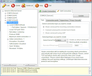
This shows the server setup on a Vista PC.
On another PC you do the same thing, but complementary. If you created a server on the first, create a client on the second. If you created a UDP connection on the first PC, you should create also a UDP connection on the second. Make sure to specify the right host IP numbers and to use the same port numbers on both PCs. Also better switch of any firewalls. I had to do that on the Vista PC before my XP PC would receive any data even though Vista did receive without any problem.
BTW, as host IP it is also possible to specify “localhost”. This way you can make serial ports on the same PC talk to each other.
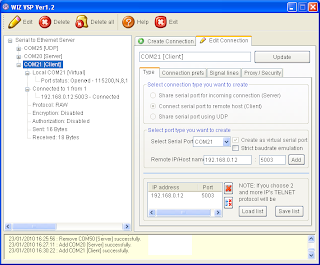
Here is the XP client that talks to the Vista PC.
To familiarize yourself with the tool I suggest to first only use virtual ports and a terminal program. This way you can type and see what happens.
Once you know how to properly setup WIZ VSP, your application can use a serial port on another PC, anywhere in the world! Or a serial device (f.i. a GPS) can transmit data to multiple hosts. I am sure you can come up with some other useful configuration. This is a very powerful tool and anyone using serial ports should get a copy of it. Now!
Oh, one more thing. Once the connections are established you can close the program without killing them.
Friday, January 15, 2010
Energy harvesting power supply
This week I came across an interesting new product from Linear Technology: the LTC3588 energy harvesting power supply intended for powering remote microcontroller systems. According to the product description this chip is a complete energy harvesting solution optimized for low energy sources, including piezoelectric transducers.
A buzzer?
The LTC3588 datasheet does mention some manufacturers of piezoelectric transducers that can be used with the chip. I looked one up: the T220-A4-503X from Piezo Systems. As I allready suspected, it is not really a buzzer. It is also more expensive than a buzzer: $125. You can buy a lot of batteries for that money, but it is probably cheaper than to send out a maintenance engineer to replace a dead battery. This particular transducer can deliver 5.4 mW RMS when it vibrates ±1.57 mm at 80 Hz. It comes as a 0.5 mm thick card of 31.8 x 63.5 mm (1.25" x 2.5") that has to be soldered with special solder (the transducer has nickel electrodes).
OK, so this kind of piezoelectric transducers is probably not for me, but the LTC3588 datasheet shows other ways of using the chip: with a solar panel or a thermoelectric transducer or as an electric field harvester.
I like the last one. It uses two 30 x 60 cm (12" x 24") sheets of copper at about 15 cm (6") from a 60 x 120 cm (2' x 4') fluorescent light fixture. At such a short distance you might as well wire the chip directly to the light fixture supply, right? Luckily the datasheet also shows you how to do that.
Yet the LTC3588 seems like a pretty interesting chip and I ordered some samples. I will let you know if I get them and if I did, what I managed to do with them.
LTC3588 datasheet
Piezo Systems
A nice introduction to piezoelectric transducers
Thursday, January 7, 2010
Accelerometers
Freescale announced this week their latest accelerometer MMA7660FC. This is a 3-axis digital output (I2C), very low power, low profile capacitive micro machined accelerometer featuring a low pass filter, compensation for 0g offset and gain errors, and conversion to 6-bit digital values at a user configurable output data rate. It offers low-power operation of 47 µA at 1 sample per second. The device can be used for sensor data changes, product orientation, and gesture detection through an interrupt pin.
Cool!
The product description ends with: "The device is housed in an extremely small 3 mm x 3 mm x 0.9 mm DFN package."
Bummer...
Elektor will present very soon its mobile 32-bit platform Sceptre which includes, amongst others, a 3D accelerometer from Freescale. For the Sceptre I have spent a lot of time looking for hand-solderable accelerometers but without success. Do easy to solder accelerometers actually exist? I guess not, but maybe someone will know of one and tell me about it. A more useful question is probably:
Do you have a technique for reliably soldering QFN or DFN packages by hand?
This question interests me very much, and, I am sure, many other people as well.
Here is a picture of the Sceptre that I sneaked out of the lab.
Hot, hot, hot!!!

This is one of the first three prototypes and it still works (one died during temperature testing). A second version that fixes some bugs and adds some improvements is on its way.
The accelerometer is the little black square in the left lower corner of the board (its a QFN unfortunately). On the top right is a Bluetooth module and if you look well enough you can see on the left an SD card sticking out from the bottom of the card. It runs from a mobile phone batterie and a charger for it is included on the board.
Stay tuned!
Subscribe to:
Posts (Atom)
