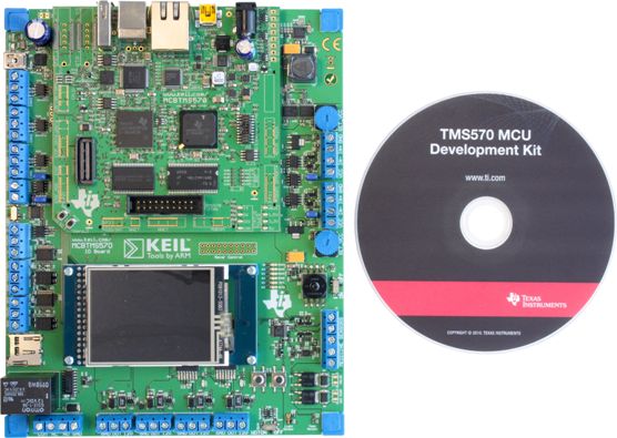
The other day a colleague asked me if I was interested in reviewing the TMS570 MCU Development Kit. This is a kit for playing with the TMS570LS20216 ARM Cortex-R4F microcontroller and when I looked at the picture of the kit available on the product page on TI web site I immediately became interested. It is a big main board with a TFT display and many connectors on which a smaller board sits. The TMS570 microcontroller is designed for use in safety critical systems and as such it includes [quote TI website] dual CPUs in lockstep, CPU and Memory Built-In Self Test (BIST) logic, ECC on both the Flash and the data SRAM, parity on peripheral memories, and loop back capability on peripheral I/O. The Floating Point CPU offers 1.6 DMIPS/MHz, and it has configurations which can run up to 160 MHz providing more than 250 DMIPS. [quote end] The TMS570LS20216 has 2 MB Flash memory and 160 KB SRAM. One might be tempted to say that this is a pretty powerful MCU.
When the kit to review arrived it turned out to be not exactly what I expected, as it was just a large USB stick. The stick is so large because otherwise the MCU in its 144LQFP package wouldn’t fit on it. It came in one of those CD/DVD boxes that we know from TI and that included besides the stick a little flash light, a DVD, a USB extension cable and a flyer with installation instructions. The installation instructions are simple: insert the DVD and do a full install. So I did.
I wrote down the amount of free disk space before launching the install and the time: 9h20. More than 30 minutes and 95 (really!) mouse clicks later the installation was complete. Looking at the free disk space left over I noticed that this demo had used a whopping 7 GB! As a comparison, my Windows XP Pro folder contains 9 GB. To be totally honest, I did this installation twice, the first time I just ran it while trying to do other things. But when the number of mouse clicks and the amazing amount of pop-up windows started bugging me I decided to redo the installation and count and measure the above mentioned parameters.
Naturally I now was pressed to see the demo's, curious to discover what a USB stick with only a few LEDs and a 5 square cm MCU on it supported by 7 GB of software had to offer. Connecting the stick to my PC worked fine, it was recognized immediately, and I started the Safety Demo Software as indicated in step 3 of the installation notes. A window with six large buttons came up and I clicked on the left upper one labelled “Safety Features”. The tool now first programmed the MCU before showing a block diagram of the chip and a list of small buttons on the left that let you generate an error event in the MCU. The error is graphically illustrated in the block diagram and a little red LED is lighted on the board.
You will have little trouble to understand that I was deeply impressed by this convincing demo so I quickly went on to try the others. I clicked the Ambient Light button and a little window with a vertical bar graph showing ambient light intensity came up. A light sensor included on the stick makes this demo possible. If you keep your hand over the stick the bar drops to a few percent and when you shine the flash light on the sensor you can get it up to 100%.
Again, Wow.
So quickly on to the next demo: the Temperature Sensor. Clicking the button opens a small window showing a graph of the temperature. According to the demo the temperature was over 30 degrees Celsius, at least 7 degrees higher than the ambient temperature, but maybe it measured closely to the MCU or the PC? Anyway, this demo was as convincing as the others.
What about the LED Light Show? Again a little window pops up and this time you can start the preprogrammed light show or toggle the six blue LEDs manually. To not spoil the surprise in case you want to buy this development stick yourself I will not tell you what happened but I can assure you that I was again deeply impressed.
If I remember correctly TI was the first to introduce the concept of USB development and evaluation sticks, but where the first one featured an MSP430 MCU that you could break off after programming and then use in your own application, this USB stick seems to be a pure product of marketing. Only 22 of the 144 pins (called “test points”) are brought out to two pin headers although a CAN bus is available too. You get a compiler too, so you can write some code for the MCU but do you really need 7 GB and 95+ mouse clicks for that?
Let us now define a benchmark for MCU development / evaluation kits so we can quickly compare the ease of use and system impact of those kits: the helloWorld (hW). The helloWorld is calculated as mds/(ds*(mc+i)) where “mds” is the highest capacity hard disk available in the year of release of the dev kit (see Wikipedia, in 2011 msb = 4 TB), “ds” stands for disk space needed by the dev kit and mc means mouse clicks needed to get an LED flashing on the dev kit and finally “i” is the number of icons & short-cuts created on the desktop (8 for this kit). With such a benchmark the flash light included in the kit would get a score of infinity because it does not occupy any disk space. The mds parameter is included to introduce an element of time in the benchmark so that it would be possible to compare helloWorld benchmarks over time. You might argue that including Eclipse in a dev kit should be a separate parameter pulling the score down, but Eclipse in itself consumes enough disk space to ensure a low benchmark anyway.
The TMS570 Microcontroller Development Stick presented here scores a value of 4 TB / 7 GB x (95 mouse clicks + 8 icons) = 5.68 helloWorld [hW].
If you have any suggestions of benchmark scores for other dev and or eval (evil?) kits, please do not hesitate to send them to me so I can publish them here.
Monday, November 28, 2011
Thursday, October 27, 2011
Reverse engineering? The new Wiring S board
In the fall of 2008 I started researching Arduino for an introductory article for Elektor. In that article I wrote that Arduino can be seen as a simplification of Wiring. The Arduino environment is very much like Wiring but slightly simplified and the Arduino Diecimila, the board of choice in 2008, was much simpler than the Wiring microcontroller board that had more I/O ports available. It is difficult to prove that the huge success of Arduino is due to this simplification, but the fact is that the current estimate is that more than 300,000 Arduino boards have been sold world-wide, which is pretty impressive.
The people behind Wiring must have been a bit jealous of this success achieved by others with their work so they started simplifying too. The result is the brand new Wiring S board that is almost the same size as an Arduino Uno. The Wiring S team apparently decided that they wanted to do things slightly different than the Arduino team, so the board looks a lot like an Arduino, but it is not compatible. Where Arduino uses mostly ATmegaXX8 controllers, the Wiring S board is based on an ATmegaXX4 controller (ATmega644 on my 1.0 board). The connectors look very similar, and are positioned in a similar way, but there are 5 instead of 4 and the pin-out is different. Also the project is open hardware, but the design files are in KiCAD instead of Eagle.
Seeeduino (left) and Wiring S (right)
It is rather interesting to see how Arduino is becoming more and more complex with programmable USB interface chips, all kinds of different processors and more connectors whereas the Wiring S board is almost like an old Arduino Diecimila but with a bigger processor. The board even offers the possibility to replace the FTDI USB/serial converter chip by an FTDI cable which brings it very close to the even older Arduino Serial. The two teams seem to be working in opposite directions.
For the people who would like to have the best of both worlds, they should use Wiring because the Wiring environment is capable of handling Arduino boards, whereas the Arduino environment does not handle Wiring boards and a Wring Play Shield is available that allows you to stick Arduino shields on the Wiring S board.
The Wiring S board is simply rectangular with its extension connectors on a 0,1” grid and 4 mounting holes placed in a logical manner. I do not like the position or the shape of the reset button; it is too hard & difficult to press. The solder side of my board was not cleansed properly and this seemed to be true for the whole batch received by my distributor. Maybe this is a pre-series problem?
Retro yellow LEDs!
Will the Wiring S meet with the same success as Arduino? Hard to say, I guess not, it is probably too late now.
The people behind Wiring must have been a bit jealous of this success achieved by others with their work so they started simplifying too. The result is the brand new Wiring S board that is almost the same size as an Arduino Uno. The Wiring S team apparently decided that they wanted to do things slightly different than the Arduino team, so the board looks a lot like an Arduino, but it is not compatible. Where Arduino uses mostly ATmegaXX8 controllers, the Wiring S board is based on an ATmegaXX4 controller (ATmega644 on my 1.0 board). The connectors look very similar, and are positioned in a similar way, but there are 5 instead of 4 and the pin-out is different. Also the project is open hardware, but the design files are in KiCAD instead of Eagle.
It is rather interesting to see how Arduino is becoming more and more complex with programmable USB interface chips, all kinds of different processors and more connectors whereas the Wiring S board is almost like an old Arduino Diecimila but with a bigger processor. The board even offers the possibility to replace the FTDI USB/serial converter chip by an FTDI cable which brings it very close to the even older Arduino Serial. The two teams seem to be working in opposite directions.
For the people who would like to have the best of both worlds, they should use Wiring because the Wiring environment is capable of handling Arduino boards, whereas the Arduino environment does not handle Wiring boards and a Wring Play Shield is available that allows you to stick Arduino shields on the Wiring S board.
The Wiring S board is simply rectangular with its extension connectors on a 0,1” grid and 4 mounting holes placed in a logical manner. I do not like the position or the shape of the reset button; it is too hard & difficult to press. The solder side of my board was not cleansed properly and this seemed to be true for the whole batch received by my distributor. Maybe this is a pre-series problem?
Will the Wiring S meet with the same success as Arduino? Hard to say, I guess not, it is probably too late now.
Friday, September 30, 2011
RS Components presents new website
If you design your own electronics circuits you have to select the best parts for your design. This can be very time consuming especially if you do not know where to look for them. For me problem parts are electromechanical parts, connectors, push-buttons, that sort of thing. What I do in those cases is look through a component distributor catalog and see if I can find something to my likes. Unfortunately these catalogs no longer reflect very well the full offering of the distributor’s products as they prefer to present them on-line.
On-line component browsing on a distributor site just is not very practical. When Digikey decided to stop distributing their paper catalog we did a little reader’s survey of which the outcome was unanimous: No!!!
If you do a search on a part you will get many useless results, but you will also miss many because the search engine didn’t find them. Typical is the table refinement option where you can tick the specifications you want. You cannot simply tick one because often the same specification is listed several times with different wording so you have to tick ‘em all. Also ticking an option will remove the parts for which this particular parameter was not specified in the first place. “Number of ways” or “polarity” can mean the same thing for a switch, but the filter only knows one of them. Voltage regulators are one example of hard to select parts. Input voltage range, output voltage range, type, etc. all parameters that can be (and are) specified in different ways making them difficult to compare.
RS Components just launched their new improved website where they put a lot of effort in improving the search engine. They told me that they now remove much more irrelevant results and they return harder to find results, but they didn’t say anything about addressing the issue of parameter homogeneity.
So is it any better now? Let’s try to pick a low-dropout voltage regulator. The RS website returns 58 results (September 30, 2011, 14:00 h CET). Filtering on “Input Voltage” only shows 19 possibilities; strange, what happened to the other 39 parts? They have no specified input voltage? I find that hard to believe for a voltage regulator.
There are three parts with an input voltage range from -1 to 40V that turn out to be three versions of the same device (UC3836/2836 from TI). There is only one device with a range of 3.5 to 36V (LTC1624 from Linear Technology) but it is not the same as the TI one although the input voltage range is inside the -1 to 40V range, so the TI part would be an option too.
The filter proposes four devices with an input voltage of 40V without a minimum value. The result is again four similar devices, again from TI, but this time the UC3834/2834. Looking up the device on the TI website I discover that TI specifies an input voltage range of 5 to 35V for this device, not 40V. So what do they specify for the UC3836 on its product page? 6 to 40V! Eh? But RS said -1 to 40V, right? Yes, but actually that is the absolute maximum range. Duh! In that case, why didn’t they use -0.3 to 36V for the LTC1624? Pears and apples, that’s what this is.
Now you may think that I spend a day or so on finding this example, but no, I didn’t. I found it while typing up this post. It was that easy, meaning that it is the same for other parts. It is still very hard to use a distributor’s website for selecting parts for a design. The new RS site does look slicker and maybe the search engine is better, but I am not sure if I will notice the difference.
BTW, did I mention that the filter button doesn’t work in Firefox? I suppose (for now) that’s just my Firefox being incorrectly set up.
On-line component browsing on a distributor site just is not very practical. When Digikey decided to stop distributing their paper catalog we did a little reader’s survey of which the outcome was unanimous: No!!!
If you do a search on a part you will get many useless results, but you will also miss many because the search engine didn’t find them. Typical is the table refinement option where you can tick the specifications you want. You cannot simply tick one because often the same specification is listed several times with different wording so you have to tick ‘em all. Also ticking an option will remove the parts for which this particular parameter was not specified in the first place. “Number of ways” or “polarity” can mean the same thing for a switch, but the filter only knows one of them. Voltage regulators are one example of hard to select parts. Input voltage range, output voltage range, type, etc. all parameters that can be (and are) specified in different ways making them difficult to compare.
RS Components just launched their new improved website where they put a lot of effort in improving the search engine. They told me that they now remove much more irrelevant results and they return harder to find results, but they didn’t say anything about addressing the issue of parameter homogeneity.
So is it any better now? Let’s try to pick a low-dropout voltage regulator. The RS website returns 58 results (September 30, 2011, 14:00 h CET). Filtering on “Input Voltage” only shows 19 possibilities; strange, what happened to the other 39 parts? They have no specified input voltage? I find that hard to believe for a voltage regulator.
There are three parts with an input voltage range from -1 to 40V that turn out to be three versions of the same device (UC3836/2836 from TI). There is only one device with a range of 3.5 to 36V (LTC1624 from Linear Technology) but it is not the same as the TI one although the input voltage range is inside the -1 to 40V range, so the TI part would be an option too.
The filter proposes four devices with an input voltage of 40V without a minimum value. The result is again four similar devices, again from TI, but this time the UC3834/2834. Looking up the device on the TI website I discover that TI specifies an input voltage range of 5 to 35V for this device, not 40V. So what do they specify for the UC3836 on its product page? 6 to 40V! Eh? But RS said -1 to 40V, right? Yes, but actually that is the absolute maximum range. Duh! In that case, why didn’t they use -0.3 to 36V for the LTC1624? Pears and apples, that’s what this is.
Now you may think that I spend a day or so on finding this example, but no, I didn’t. I found it while typing up this post. It was that easy, meaning that it is the same for other parts. It is still very hard to use a distributor’s website for selecting parts for a design. The new RS site does look slicker and maybe the search engine is better, but I am not sure if I will notice the difference.
BTW, did I mention that the filter button doesn’t work in Firefox? I suppose (for now) that’s just my Firefox being incorrectly set up.
Open World Forum 2011
Saturday 24 September I joined two of my colleagues at the Experiment Day of the Open World Forum in Paris. Since it took place not far from the Crazy Horse I had no difficulties in finding the venue. My colleagues had come the day before by car because they had to bring books and magazines and especially the OSPV1, our open-source auto-balancing two-wheeled vehicle that we were to present.
The OSPV1 self balancing vehicle
The Forum was held in a rather high-class venue that had been paid for by a very impressive collection of sponsors in one of those rich “quartiers” of Paris where you get more easily run over by a Ferrari then by a Peugeot. The Open World Forum is all about Open Source; here the first question people ask you about a product is what license it is released under. I tend to associate Open Source with financially impaired people (i.e. students) with beards and spectacles hacking away in poorly furnished rooms and so it seems strange to actually meet these people (who came indeed pretty close to how I always had imagined them) in such a high-end place. Free lunch & drinks for everybody, all you can eat sushi in the pressroom, a real “we don’t care about money we only care about Open Source” attitude.
The ambiance was quite arty and inspiring with many great projects being showed off. It was interesting to meet so many people working with electronics without having a formal electronics education. They simply define an objective and then see what they can do with plug ‘n’ play electronics like Arduino to achieve it. These are electronics users (or should I say consumers) that embed ready-made building blocks in their projects.
I was a bit disappointed by the number of visitors. For some reason too few interested people made it on this sunny day to avenue George V. Maybe they didn’t have the money for a metro ticket? Make sure you visit next time, it is definitely worth skipping a lunch to save some money to pay for the trip.
The Forum was held in a rather high-class venue that had been paid for by a very impressive collection of sponsors in one of those rich “quartiers” of Paris where you get more easily run over by a Ferrari then by a Peugeot. The Open World Forum is all about Open Source; here the first question people ask you about a product is what license it is released under. I tend to associate Open Source with financially impaired people (i.e. students) with beards and spectacles hacking away in poorly furnished rooms and so it seems strange to actually meet these people (who came indeed pretty close to how I always had imagined them) in such a high-end place. Free lunch & drinks for everybody, all you can eat sushi in the pressroom, a real “we don’t care about money we only care about Open Source” attitude.
The ambiance was quite arty and inspiring with many great projects being showed off. It was interesting to meet so many people working with electronics without having a formal electronics education. They simply define an objective and then see what they can do with plug ‘n’ play electronics like Arduino to achieve it. These are electronics users (or should I say consumers) that embed ready-made building blocks in their projects.
I was a bit disappointed by the number of visitors. For some reason too few interested people made it on this sunny day to avenue George V. Maybe they didn’t have the money for a metro ticket? Make sure you visit next time, it is definitely worth skipping a lunch to save some money to pay for the trip.
Friday, August 26, 2011
Everything you always wanted to know about klystrons and traveling wave tubes (but were afraid to ask)
Most of the time this blog is about embedded electronics, but if I come across something interesting that is electronic but not directly related I will talk about it here too. Therefore, this time I will write about a book with the impressive title: Klystrons, Traveling Wave Tubes, Magnetrons, Crossed-Field Amplifiers, and Gyrotrons It is written by A.S. Gilmour, Jr. of the State University of New York, Buffalo and the book is edited by Artech House. The editor presents it as: The culmination of the author’s 50 years of industry experience, this authoritative resource offers engineers a thorough understanding of the operations and major classes of microwave tubes.
This field of electronics definitely has the coolest named devices of the industry and I sure would like to use a gyro-twystron once in my life, just so that I can say I did. Controlled by an Arduino maybe? Anyway, I’ve read this book and found it, to my surprise, quite fascinating. 800 pages about electron guns, exotic materials to make cathodes with, magnetic and electric fields and incredible amounts of power, actually this book is more about physics than about electronics. What I really liked about it was the mix of well established theory and experimental physics. The author does a pretty good job, as far as I can judge, at relating the complete history of magnetrons and the like. From the initial idea to the many tweaks that took the devices to where they are now, everything is described and it all feels very hands-on and experimental.
For the people that have to really study this material the book contains a wealth of drawings, diagrams, formulas and equations with derivations. I don’t think you will be able to actually construct a working megawatt gyrotron just by reading this book, it lacks the electronics, but it definitely will get you started. If you don’t care for the math, you can skip it all. Since the book introduces many terms the reader may be unfamiliar with it includes a glossary at the end. Your knowledge of vacuum pumps is a bit rusty? Read appendix B on vacuum technology. Appendix C gets you up to speed with magnetics.
I have only one negative comment about this book: the illustration the text is talking about is almost always on the back side of the page you are reading. Since there are many drawings you keep flipping back and forth between the drawing and its description.
This book does not introduce new theory but it is bound to become a standard reference for the serious high-power RF/radar engineer who has always a klystron lying around on his desk.
This field of electronics definitely has the coolest named devices of the industry and I sure would like to use a gyro-twystron once in my life, just so that I can say I did. Controlled by an Arduino maybe? Anyway, I’ve read this book and found it, to my surprise, quite fascinating. 800 pages about electron guns, exotic materials to make cathodes with, magnetic and electric fields and incredible amounts of power, actually this book is more about physics than about electronics. What I really liked about it was the mix of well established theory and experimental physics. The author does a pretty good job, as far as I can judge, at relating the complete history of magnetrons and the like. From the initial idea to the many tweaks that took the devices to where they are now, everything is described and it all feels very hands-on and experimental.
For the people that have to really study this material the book contains a wealth of drawings, diagrams, formulas and equations with derivations. I don’t think you will be able to actually construct a working megawatt gyrotron just by reading this book, it lacks the electronics, but it definitely will get you started. If you don’t care for the math, you can skip it all. Since the book introduces many terms the reader may be unfamiliar with it includes a glossary at the end. Your knowledge of vacuum pumps is a bit rusty? Read appendix B on vacuum technology. Appendix C gets you up to speed with magnetics.
I have only one negative comment about this book: the illustration the text is talking about is almost always on the back side of the page you are reading. Since there are many drawings you keep flipping back and forth between the drawing and its description.
This book does not introduce new theory but it is bound to become a standard reference for the serious high-power RF/radar engineer who has always a klystron lying around on his desk.
Tuesday, August 16, 2011
Wireless audio over 2.4 GHz
Just before the summer my contact at Texas Instruments had the excellent idea to sent me a CC85XXDK-HEADSET development kit. This is a PurePath Wireless Headset Development Kit to evaluate the new wireless audio products from TI based on the CC85xx family of RF micro-controllers. Due to a lack of time I didn't have the opportunity to write about it earlier, but I did give it a try and was impressed.
The kit contains two identical cards, one of which is configured as a master, the other as a slave. Both contain a 2.4 GHz radio and once paired (a simple operation) you can stream high quality stereo audio from the master to the slave. This works exceptionally well according to my non audiophile ears. The cards are each powered from one 1.72 Wh rechargeable li-ion battery, so it is a totally portable system. Charging the batteries is done by hooking the boards up to a USB port. TI claims a continues operation of 22 hours for this system.
I gave it a try in my garden and managed a Line of sight (LOS) distance of some 45+ meters (then I ran out of garden). It will probably go a bit further when the master is higher up from the ground. Occasionally the receiver has drop-outs, then it suddenly goes from full quality audio to complete silence, but this happens only at greater distances or when the data path becomes obstructed. Never did I hear any garbage out of the headphones.
Included in the kit is a little CC Debugger pod (with a funny rubbery feel) that you can use to reprogram the boards. This pod lets you reprogram and configure the boards using a tool called PurePath Wireless Configurator. The purpose of this tool is a bit unclear to me as there doesn't seem to be a whole lot that you can configure, but it is probably useful when you develop your own systems.
If you need a high quality wireless audio link in your system, the CC85xx is definitely worth a look!
The kit contains two identical cards, one of which is configured as a master, the other as a slave. Both contain a 2.4 GHz radio and once paired (a simple operation) you can stream high quality stereo audio from the master to the slave. This works exceptionally well according to my non audiophile ears. The cards are each powered from one 1.72 Wh rechargeable li-ion battery, so it is a totally portable system. Charging the batteries is done by hooking the boards up to a USB port. TI claims a continues operation of 22 hours for this system.
I gave it a try in my garden and managed a Line of sight (LOS) distance of some 45+ meters (then I ran out of garden). It will probably go a bit further when the master is higher up from the ground. Occasionally the receiver has drop-outs, then it suddenly goes from full quality audio to complete silence, but this happens only at greater distances or when the data path becomes obstructed. Never did I hear any garbage out of the headphones.
Included in the kit is a little CC Debugger pod (with a funny rubbery feel) that you can use to reprogram the boards. This pod lets you reprogram and configure the boards using a tool called PurePath Wireless Configurator. The purpose of this tool is a bit unclear to me as there doesn't seem to be a whole lot that you can configure, but it is probably useful when you develop your own systems.
If you need a high quality wireless audio link in your system, the CC85xx is definitely worth a look!
Thursday, August 4, 2011
Chasing tornadoes
This is my last post live from NIWeek 2011, my plane leaves in a few hours and the show is finished now anyway. Looking back I had a good show with many interesting and exciting! encounters, technical as well as human. Look, I even made a friend.
He is great because he plays soccer and he is as good at it as I am. I bet he dances like me too.
Today was the last keynote during which several impressive student projects were presented including the world-wide winning (www) project in the student project competition. This was a 3D display that you can actually build at home thanks to its extraordinary simplicity.
The keynote ended with a presentation by Tim Samaras who chases tornadoes for a living. Tim showed some very spectacular footage of tornadoes but also of lightning, because that is his second hobby. He and his team film lightning with very high-speed cameras so that you can actually see how the lightning makes its way down to earth. Wow.
With a bit of luck I will be back here in Austin, Texas next year. If so, maybe see you then or there!
He is great because he plays soccer and he is as good at it as I am. I bet he dances like me too.
Today was the last keynote during which several impressive student projects were presented including the world-wide winning (www) project in the student project competition. This was a 3D display that you can actually build at home thanks to its extraordinary simplicity.
The keynote ended with a presentation by Tim Samaras who chases tornadoes for a living. Tim showed some very spectacular footage of tornadoes but also of lightning, because that is his second hobby. He and his team film lightning with very high-speed cameras so that you can actually see how the lightning makes its way down to earth. Wow.
With a bit of luck I will be back here in Austin, Texas next year. If so, maybe see you then or there!
Subscribe to:
Posts (Atom)